Infrared Remote Extender

This project sprang from the need to be able to remotely control audio-visual equipment placed inside cupboards. RF-based commercial units such as those used for home theatre were found to be overkill for this application. The circuit is based on a commonly available infrared receiver module (IRX1) and a PIC12F675 microcontroller (IC1) – see circuit. Most infrared standards specify a nominal 38kHz carrier signal for data transmission, which the module receives and demodulates.

Circuit diagram:
Infrared Remote Extender Circuit Diagram
Digital data output:

The digital data output from the module is fed into GP2 (pin 5) of the PIC micro, where it’s received by the PIC program and duplicated on output GP1 (pin 6). This flashes the "Signal" LED to give a visual indication that the extender is receiving the remote control’s transmissions.

Copyright: Silicon Chip Magazine

Simple Infrared Control Extender

Lots of consumer electronic equipment like TV sets, VCRs, CD and DVD players employs infrared remote control. In some cases, it is desirable to extend the range of the available control and this circuit fits the bill, receiving the IR signal from your remote control and re-transmitting it, for example, around a corner into another room. Photodiode D4 is connected to the inverting input of a 741 opamp through resistor R2 and capacitor C1. Since the BPW41 photodiode (from Vishay/Telefunken) needs to be reverse-biased to turn light energy into a corresponding voltage, it is also connected to the positive supply rail via R1. The non-inverting input of the ‘741 is held at half the supply voltage by means of equal resistors R3 and R4.

Circuit diagram:
Simple Infrared Control Extender Circuit Diagram

The opamp is followed by a BD240 after-burner transistor capable of supplying quite high current pulses through IR LEDs D2 and D3. However, the pulsed current through the LD274s should not exceed 100 mA or so, hence a fixed resistor is used in series with preset P1. D1 is an ordinary visible-light LED that flashes when an IR signal is received from the remote. With regard to the setting of P1, do not make the IRED current higher than necessary to reliably reach the final destination of the IR signal. Also, the currents mentioned above are peak levels due to the small duty factor of the IR pulses, the average current drawn from the battery will be much smaller. The directivity of the IR LEDs and consequently the range of the control extender may be increased by fitting the devices with reflective caps.
Author: Raj. K. Gorkhali - Copyright: Elektor Electronics July-August 2004

Infrared Remote Receiver Has Four Outputs

This circuit enables any infrared (IR) remote control to control the outputs of a 4017 decade counter. It's quite simple really and uses a 3-terminal IR receiver (IRD1) to pick up infrared signals from the transmitter. IRD1's output is then coupled to NPN transistor Q1 via a 220nF capacitor. Transistor Q1 functions as a common-emitter amplifier with a gain of about 20, as set by the ratio of its 10kO collector resistor to its 470O emitter resistor. Q1 in turn triggers IC1, a 4047 monostable which in turn clocks a 4017 decade counter (IC2).

Circuit diagram:

Basically, IC1 provides a clock pulse to IC2 each time a remote control button is pressed. If you don't wish to use all 10 outputs from IC2, simply connect the first unused output to pin 15 (MR). In this case, only the first four outputs (O0-O3) of the counter are used and so the O4 output is connected to pin 15 to reset the counter on the fifth button press. Power for the circuit is derived from the mains via a transformer and bridge rectifier which produces about 15-27V DC. This is then fed to 3-terminal regulators REG1 & REG2 to derive +12V and +5V supply rails.
Author: Fred Edwards - Copyright: Silicon Chip Electronics

On-off Infrared Remote Control

Most homes today have at least a few infrared remote controls, whether they be for the television, the video recorder, the stereo, etc. Despite that fact, who among us has not cursed the light that remained lit after we just sat down in a comfortable chair to watch a good film? This project proposes to solve that problem thanks to its original approach. In fact, it is for a common on/off switch for infrared remote controls, but what differentiates it from the commercial products is the fact that it is capable of working with any remote control.

Therefore, the first one you find allows you to turn off the light and enjoy your movie in the best possible conditions. The infrared receiver part of our project is entrusted to an integrated receiver (Sony SBX 1620-52) which has the advantage of costing less than the components required to make the same function. After being inverted by T1, the pulses delivered by this receiver trigger IC2a, which is nothing other than a D flip-flop configured in monostable mode by feeding back its output Q on its reset input via R4 and C3. The pulse that is produced on the output Q of IC.2A makes IC.2B change state, which has the effect of turning on or turning off the LED contained in IC3.

Circuit diagram:
On-off Infrared Remote Control Circuit Diagram

This circuit is an opto triac with zero-crossing detection which allows our setup to accomplish switching without noise. It actually triggers the triac T2 in the anode where the load to be controlled is found. The selected model allows us to switch up to 3 amperes but nothing should stop you from using a more powerful triac if this model turns out to be insufficient for your use. In order to reduce its size and total cost, the circuit is powered directly from the mains using capacitor C5 which must be a class X or X2 model rated at 230 volts AC.

This type of capacitor, called ‘self-healing’, is the only type we should use today for power supplies that are connected to ground. ‘Traditional’ capacitors, rated at 400 volts, do not really have sufficient safety guarantees in this area. Considering the fact that the setup is connected directly to the mains, it must be mounted in a completely insulated housing. A power outlet model works very well and can easily be used to inter-space between the grounded wall outlet and that of the remote control device.

Based on this principle, this setup reacts to any infrared signal and, as we said before, this makes it compatible with any remote control. On the other hand, it has a small disadvantage which is that sometimes it might react to the ‘normal’ utilization of one of these, which could be undesirable. To avoid that, we advise you to mask the infrared receiver window as much as possible so that it is necessary to point the remote control in its direction in order to activate it.
Author: Christian Tavernier - Copyright: Elektor Electronics Magazine

Wireless On-Off Switch

Small and simple circuit, Suitable for home appliances

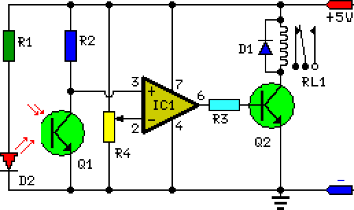
Normally home appliances are controlled by means of switches, sensors, etc. However, physical contact with switches may be dangerous if there is any shorting. The circuit described here requires no physical contact for operating the appliance. You just need to move your hand between the infrared LED (D2) and the phototransistor (Q1). The infrared rays transmitted by D2 is detected by the phototransistor to activate the hidden lock, flush system, hand dryer or else. This circuit is very stable and sensitive compared to other AC appliance control circuits. It is simple, compact and cheap. Current consumption is low in milliamperes. The circuit is built around an IC CA3140, D2, phototransistor and other discrete components.
Circuit Diagram:


Parts:
R1 = 470R
R2 = 100K
R3 = 3.3K
R4 = 10K
D1 = 1N4007
D2 = IR LED
Q1 = L14F1
RL = 5Vdc Relay
IC = CA3140
Q2 = BC548

Circuit Operation:
When regulated 5V is connected to the circuit, D2 emits infrared rays, which are received by phototransistor Q1 if it is properly aligned. The collector of Q1 is connected to non-inverting pin 3 of IC1. Inverting pin 2 of IC1 is connected to voltage-divider preset R4. Using preset R4 you can vary the reference voltage at pin 2, which also affects sensitivity of the phototransistor. Op-amp IC1 amplifies the signal received from the phototransistor. Resistor R3 controls the base current of transistor BC548 (Q2). The high output of IC1 at pin 6 drives transistor Q2 to energies relay RL1 and switch on the appliance, say, hand dryer, through the relay contacts. The working of the circuit is simple. In order to switch on the appliance, you simply interrupt the infrared rays falling on the phototransistor through your hand. During the interruption, the appliance remains on through the relay. When you remove your hand from the infrared beam, the appliance turns off through the relay. Assemble the circuit on any general-purpose PCB. Identify the resistors through colour coding or using the multimeter. Check the polarity and pin configuration of the IC and mount it using base. After soldering the circuit, connect +5V supply to the circuit.

Source : www.electronicsforu.com

RC (Remote Control) Switch

It is sometimes necessary for an RC (remote control) model to contain some kind of switching functionality. Some things that come to mind are lights on a model boat, or the folding away of the undercarriage of an aeroplane, etc. A standard solution employs a servo, which then actually operates the switch. Separate modules are also available, which may or may not contain a relay. A device with such functionality is eminently suitable for building yourself. The schematic shows that it can be easily realised with a few standard components.

Picture of the project:
RC Switch Circuit

The servo signal, which consists of pulses from 1 to 2 ms duration, depending on the desired position, enters the circuit via pin 1 of connector K1. Two buffers from IC2 provide the necessary buffering after which the signal is differentiated by C2. This has the effect that at each rising edge a negative start signal is presented to pin 2 of IC1. D1 and R4 make sure that at the falling edge the voltage at pin 2 of IC2 does not become too high. IC1 (TLC555) is an old faithful in a CMOS version.

A standard version (such as the NE555) works just as well, but this IC draws an unnecessarily high current, while we strive to keep the current consumption as low as possible in the model. The aforementioned 555 is configured as a one-shot. The pulse-duration depends on the combination of R2/C1. Lowering the voltage on pin 5 also affects the time. This results in reducing the length of the pulse. In this circuit the pulse at the output of IC will last just over 1.5 ms when T1 does not conduct.

Circuit diagram:
RC Switch Circuit Diagram

When T1 does conduct, the duration will be a little shorter than 1.5 ms. We will explain the purpose of this a little later on. Via IC2.C, the fixed-length pulse is, presented to the clock input of a D-flip-flop. As a consequence, the flip-flip will remember the state of the input (servo signal). The result is that when the servo-pulse is longer than the pulse form the 555, output Q will be high, otherwise the output will be low. It is possible, in practice, that the servo signal is nearly the same length as the output from the 555.

A small amount of variation in the servo signal could therefore easily cause the output to ‘chatter’, that is, the output could be high at one time and low the next. To prevent this chatter there is feedback in the form of R1, R3 and T1. This circuit makes sure that when the flip-flip has decided that the servo-pulse is longer than the 555’s pulse (and signals this by making output Q high), the pulse duration from the 555 is made a little shorter. The length of the servo-signal will now have to be reduced by a reasonable amount before the servo-pulse becomes shorter than the 555’s pulse.

Parts and PCB layout:
Parts and PCB layout Of RC Switch

The moment this happens, T1 will stop conducting and the mono-stable time will become a little longer. The servo-pulse will now have to be longer by a reasonable amount before the flip-flip changes back again. This principle is called hysteresis. Jumper JP1 lets you choose between the normal or inverted output signals. Buffers IC2.D through to IC2.F together with R5 drive output transistor T2, which in turn drives the output. Note that the load may draw a maximum current of 100 mA. Diode D2 has been added so that inductive loads can be switched as well (for example, electrically operated pneu-matic valves).

COMPONENTS LIST
Resistors:
R1 = 470k
R2 = 150k
R3 = 47k
R4 = 100k
R5 = 4k7
Capacitors:
C1 = 10nF
C2 = 1nF
C3,C4 = 100nF
Semiconductors:
D1 = BAT85 or similar Schottky diode
D2 = 1N4148
IC1 = CMOS 555 (e.g., TLC555 or ICM7555)
IC2 = 4049
IC3 = 4013
T1,T2 = BC547B
Miscellaneous:
JP1 = jumper with 3-way pinheader
K1 = servo cable
K2 = 2-way pinheader or 2 solder pins
Author: Paul Goossens - Copyright: Elektor Electronics

Simple infrared remote control extender

This ultra-simple remote control extender is ideal for use with a hidden video recorder. The recorder is a Panasonic NV-SD200 and is used as part of a camera surveillance system. A PICAXE-08-based circuit is used to detect events and control the recorder. It also flashes a LED near the monitor to indicate the number of events since last viewing.
Click for larger image

Strangely, the NV-SD200 model refused to work with a number of commercial infrared remote control extenders, hence the need for this design. As a bonus, it uses less power than a traditional extender (no plugpacks) and the remote can still be used in the normal manner.

As shown, an additional 5mm infrared LED is mounted directly in front of the equipment to be controlled. This is cabled back to a convenient location near the monitor and terminated in a 3.5mm plug.

To modify the remote control unit, break the circuit to the anode of the existing infrared LED and wire in a 3.5mm headphone socket. In most cases, the LED will be accessible without dismantling the circuit board. The purpose of the socket is to allow the existing infrared LED to operate normally when the jack is unplugged.

If the socket won’t fit inside the case, then a very short flying lead with a moulded in-line socket can be used instead. By using light-duty figure-eight cable, the transmitting LED could be 30m or more from the hand-held remote control without problems.