Video Tracer For Trouble-Shooting

This circuit was designed as an aid to installers and maintainers of video systems. It is basically a video sync separator (IC1) followed by a LED and buzzer driver (IC2, Q1 & Q2). In use, the device is connected to a video cable and if there is video present, the LED will flash at about 10Hz. If there is no video, the LED flashes briefly every couple of seconds. A buzzer can also be switched in to provide an audible indication. The buzzer is particularly useful when tracing cabling faults or trying to find a correct cable amongst many, where it is difficult to keep an eye on the LED.

Another use for the buzzer option is to provide a video fault indication. For example, it could be inserted in bridging mode, with switch S1 in high impedance mode (position 2) across a video line and set to alarm when there is no video present. If someone pulls out a cable or the video source is powered off, the alarm would sound. IC1 is a standard LM1881 video sync separator circuit and 75Ω termination can be switched in or out with switch S1a. The other pole of the switch, S1b, turns on the power. The composite sync output at pin 1 is low with no video input and it pulses high when composite sync is detected.

Circuit diagram:


These pulses charge a 100nF capacitor via diode D1. When there is no video at the input, oscillator IC2b is enabled and provides a short pulse every couple of seconds to flash the LED. The duty cycle is altered by including D2, so that the discharge time for the 10μF capacitor is much shorter than the charge time. The short LED pulse is used as a power-on indicator drawing minimal average current. When video is present at the input, IC2b is disabled and IC2d is enabled. The output of IC2d provides a 10Hz square wave signal to flash the LED. The buzzer is controlled by switch S2. In position 2 the buzzer will sound when there is video at the input and in position 1 the buzzer will sound when there is no video at the input.
Author: Leon Williams - Copyright: Silicon Chip Electronics

NTSC-PAL TV Signal Identifier

This circuit is able to identify PAL and NTSC video signals. Its output is high for an NTSC signal and low if the signal is PAL. This output signal can be used, for example, to automatically switch in a colour subcarrier converter or some other device while an NTSC signal is being received. One application is for the reception from satellites of 'free-to-air' TV signals, which in Australia generally contain a mixture of 625-line PAL and 525-line NTSC programs. Operation of the circuit is as follows. IC1 is an LM1881 video sync separator which takes the video input signal and generates vertical synchronisation pulses.

For an NTSC signal, these pulses are 16.66ms apart, corresponding to the 60Hz field rate, while for a PAL signal they are 20ms apart, corresponding to the 50Hz field rate. The vertical sync pulses are fed into IC2a, the first of two dual retriggerable monostable multivibrators in the 74HC123A. IC2a has a period of very close to 17.9ms, set by the 200kO resistor and 0.22µF capacitor at pins 14 & 15. Because the monostable is retriggerable, NTSC sync pulses arriving every 16.66ms will keep its Q output, at pin 13, high.

Circuit diagram:


However PAL sync pulses arriving every 20ms will allow the Q output to go low after 17.9ms, before being triggered high again 2.1ms later. Thus an NTSC signal will give a constant high output while a PAL signal will result in a train of pulses 2.1ms wide. The Q output from IC2a is fed to the inverting input of IC2b, the second monostable, which has a period of about 0.5s, as set by the 270kO resistor and 4.7µF tantalum capacitor at pins 6 & 7. With its input constantly high, resulting from an NTSC signal, IC2b is not triggered and its Q output remains low.

However, the pulse train from a PAL signal will constantly retrigger it, so its Q output will remain high. The period of IC2b also effectively makes it a low-pass filter which removes spurious switching due to any input glitches. The output signal is taken from the Q-bar (inverted) output, so that an NTSC signal gives a high output, while PAL gives low. For the particular application for which the circuit was developed, diode D1 and the resistor network shown drive the base of an NPN switching transistor and relay. A dual-colour 3-lead LED can also be fitted to indicate NTSC (red) or PAL (green). Note that with no video input, the output signal is high and will indicate NTSC.
Source: Extreme Circuits

Video Amplifier

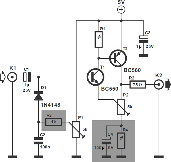
The video amplifier in the diagram is a well-known design. Simple, yet very useful, were it not for the ease with which the transistors can be damaged if the potentiometers (black level and signal amplitude) are in their extreme position. Fortunately, this can be obviated by the addition of two resistors. If in the diagram R3 and R4 were direct connections, as in the original design, and P1 were fully clockwise and P2 fully anticlockwise, such a large base current would flow through T1 that this transistor would give up the ghost.

Circuit diagram:


Moreover, with the wiper of P2 at earth level, the base current of T2 would be dangerously high. Resistors R3 and R4 are sufficient protection against such mishaps, since they limit the base currents to a level of not more than 5 mA. Shunt capacitor C4 prevents R4 having an adverse effect on the amplification.
Author: L.A.M. Prins
Copyright: Elektor Electronics

Video Isolator Circuit Diagram

These days many more audio-visual devices in the home are connected together. This is especially the case with the TV, which may be connected to a DVD player, a hard disk recorder, a surround-sound receiver and often a PC as well. This often creates a problem when earth loops are created in the shielding of the video cables, which may cause hum and other interference. The surround-sound receiver contains a tuner that takes its signal from a central aerial distribution system.

The TV is also connected to this and it’s highly likely that the PC has a TV-card, which again is connected to the same system. On top of this, there are many analogue connections between these devices, such as audio cables. The usual result of this is that there will be a hum in the audio installation, but in some cases you may also see interference on the TV screen.
The ground loop problem can be overcome by galvanically isolating the video connections, for example at the aerial inputs of the surround-sound receiver and the TV.

Special adaptors or filters are sold for this purpose, known as video ground loop isolators. Good news: such a filter can also be easily made at home by yourself. There are two ways in which you can create galvanic isolation in a TV cable. The first is to use an isolating transformer with two separate windings. The other is to use two coupling capacitors in series with the cable. The latter method is easily the simplest to implement and generally works well enough in practice. The simplest way to produce such a ‘filter’ is as an in-line adapter, so you can just plug it onto either end of a TV aerial cable.

Diagram and snapshoot:

Video Isolator Circuit

The only requirements are a male and female coax plug and two capacitors. The latter have to be suitable for high-frequency applications, such as ceramic or MKT types. It is furthermore advisable to choose types rated for high voltages (400 V), since the voltages across these capacitors can be higher than you might expect (A PC that isn’t connected to the mains Earth can have a voltage as high as 115 V (but at a very low, safe current), caused by the filter capacitors in its power supply.

These capacitors don’t need to be high value ones, since they only have to pass through frequencies above about 50 MHz. Values of 1 nF or 2.2 nF are therefore sufficient. To make the isolator you should connect one capacitor between the two earth connections of the coax plugs and the other between the two signal connections. The mechanical construction has to be sturdy enough such that the connections to the capacitors won’t break whenever the inline adapter is removed forcibly.

A good way to do this is to make a cover from a piece of PVC piping for the central part. Wrap aluminium foil round the outside and connect it to one of the plugs, so that the internal parts are properly shielded from external interference. Make sure that the aluminium foil doesn’t make contact with the other plug, otherwise you lose the isolation. The majority of earth loops will disappear when you connect these filters to all used outputs of the central aerial distribution system where the signal enters the house.
Harry Baggen
Elektor Electronics 2008

Cable TV amplifier

This is a very simple cable TV amplifier using two transistors. This amplifier circuit is most suitable for cable TV systems using 75 Ohm coaxial cables and works fine up to 150MHz. Transistor T1 performs the job of amplification. Up to 20dB gain can be expected from the circuit.T2 is wired as an emitter follower to increase current gain.
assembled on a Vero board.
  • Use 12V DC for powering the circuit.
  • Type no of the transistors are not very critical.
  • Any medium power NPN RF transistors can be used in place of T1 and T2.
  • This is just an elementary circuit. Do not compare it with high quality Cable TV amplifiers available in the market.

VGA to BNC Adapter (Converter)

There are monitors which only have three BNC inputs and which use composite synchronization (‘sync on green’). This circuit has been designed with these types of monitor in mind. As can be seen, the circuit has been kept very simple, but it still gives a reasonable performance. The principle of operation is very straightforward. The RGB signals from the VGA connector are fed to three BNC connectors via AC-coupling capacitors. These have been added to stop any direct current from entering the VGA card. A pull-up resistor on the green output provides a DC offset, while a transistor (a BS170 MOSFET) can switch this output to ground. It is possible to get synchronisation problems when the display is extremely bright, with a maximum green component.
In this case the value of R2 should be reduced a little, but this has the side effect that the brightness noticeably decreases and the load on the graphics card increases. To keep the colour balance the same, the resistors for the other two colors (R1 en R3) have to be changed to the same value as R2. An EXOR gate from IC1 (74HC86) combines the separate V-sync and H-sync signals into a composite sync signal. Since the sync in DOS-modes is often inverted compared to the modes commonly used by Windows, the output of IC1a is inverted by IC1b. JP1 can then by used to select the correct operating mode. This jumper can be replaced by a small two-way switch, if required.
This switch should be mounted directly onto the PCB, as any connecting wires will cause a lot of interference. The PCB has been kept as compact as possible, so the circuit can be mounted in a small metal (earthed!) enclosure. With a monitor connected the current consumption will be in the region of 30 mA. A 78L05 voltage regulator provides a stable 5 V, making it possible to use any type of mains adapter, as long as it supplies at least 9 V. Diode D2 provides protection against a reverse polarity. LED D1 indicates when the supply is present. The circuit should be powered up before connecting it to an active VGA output, as otherwise the sync signals will feed the circuit via the internal protection diodes of IC1, which can be noticed by a dimly lit LED. This is something best avoided.

Resistors:
R1,R2,R3 = 470Ω
R4 = 100Ω
R5 = 3kΩ3
Capacitors:
C1,C3,C5 = 47µF 25V radial
C2,C4,C6,C7,C10 = 100nF ceramic
C8 = 4µF7 63V radial
C9 = 100µF 25V radial
Semiconductors:
D1 = LED, high-efficiency
D2 = 1N4002
T1 = BS170
IC1 = 74HC86
IC2 = 78L05
Miscellaneous:
JP1 = 3-way pinheader with jumper
K1 = 15-way VGA socket (female), PCB mount (angled pins)
K2,K3,K4 = BNC socket (female), PCB mount, 75Ω