Small DC Motor Control Using PWM

Small DC motors are efficiently controlled using pulse-width modulation (PWM) method. The circuit described here is built around an LM324 low-power quad-operational amplifier. Of the four op-amps (operational amplifiers) available in this IC, two are used for triangular wave generator and one for comparator. Op-amp N2 generates a 1.6kHz square wave, while op-amp N1 is configured as an integrator. The square wave output of N2 at its pin 14 is fed to the inverting input (pin 2) of N1 through resistor R1. As N1 is configured as an integrator, it outputs a triangular wave of the same frequency as the square wave. The triangular wave is fed to pin 5 of op-amp N3, which is configured as a comparator.

Small DC Motor Control Circuit Diagram :

Small DC Motor Control Cirucit diagram

The reference voltage at pin 6 of the comparator is fixed through the potential divider arrangement formed by potmeter VR1 and resistors R4 and R5. It can be set from –6V (lowermost position of VR1) to +6V (uppermost position of VR1).
The triangular wave applied at pin 5 of N3 is compared with the reference voltage at its pin 6. The output at pin 7 is about +12V when the voltage at pin 5 is greater than the voltage at pin 6. Similarly, the output at pin 7 is about -12V when the voltage at pin 5 is lower than the voltage at pin 6.

The output from comparator N3 is the gate voltage for n-channel MOSFET (T1). T1 switches on when the gate voltage is positive and switches off when the gate voltage is negative. Setting of the reference voltage therefore controls the pulse-width of the motor. When T1 is switched on for a longer period, the pulse width will be wider, which means more average DC component and faster speed of the motor. Speed will be low when the pulse width is small. Thus potmeter VR1 controls the speed of the motor.

Assemble the circuit on a general-purpose PCB and enclose in a suitable cabinet. The circuit requires ±12V power supply for its working. It can also be modified to control the speed of a 6V or 24V DC motor.

Author : Stutee Saxena - Copyright: EFY

12V Speed Controller/Dimmer

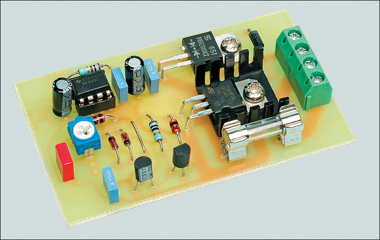
This handy circuit can be used as a speed controller for a 12V motor rated up to 5A (continuous) or as a dimmer for a 12V halogen or standard incandescent lamp rated up to 50W. It varies the power to the load (motor or lamp) using pulse width modulation (PWM) at a pulse frequency of around 220Hz.  SILICON CHIP has produced a number of DC speed controllers over the years, the most recent being our high-power 24V 40A design featured in the March & April 2008 issues. Another very popular design is our 12V/24V 20A design featured in the June 1997 issue and we have also featured a number of reversible 12V designs.


Project Image :

12v-speed-controllerdimmer pro

 12V Speed Controller/Dimmer Project Image


For many applications though, most of these designs are over-kill and a much simpler circuit will suffice. Which is why we are presenting this basic design which uses a 7555 timer IC, a Mosfet and not much else. Being a simple design, it does not monitor motor back-EMF to provide improved speed regulation and nor does it have any fancy overload protection apart from a fuse. However, it is a very efficient circuit and the kit cost is quite low.


Parts layout:

12v-speed-controllerdimmer2_Parts layout

Connection diagram:

12v-speed-controllerdimmer3_Connection diagram


There are many applications for this circuit which will all be based on 12V motors, fans or lamps. You can use it in cars, boats, and recreational vehicles, in model boats and model railways and so on. Want to control a 12V fan in a car, caravan or computer? This circuit will do it for you. The circuit uses a 7555 timer (IC1) to generate variable width pulses at about 210Hz. This drives Mosfet Q3 (via transistors Q1 & Q2) to control the speed of a motor or to dim an incandescent lamp.


Circuit diagram :

12v-speed-controllerdimmer Circuit diagram

12V Speed Controller/Dimmer Circuit Diagram


While the circuit can dim 12V halogen lamps, we should point out that dimming halogen lamps is very wasteful. In situations where you need dimmable 12V lamps, you will be much better off substituting 12V LED lamps which are now readily available in standard bayonet, miniature Edison screw (MES) and MR16 halogen bases. Not only are these LED replacement lamps much more efficient than halogen lamps, they do not get anywhere near as hot and will also last a great deal longer.

Source : Silicon Chip

Electronic Starter For Single-Phase Motor

Anovel single-phase electronic starter circuit meant for 0.5HP and 1HP motors is presented here. It incorporates both overload and short-circuit protections. A special cur-rent-sensing device has been added in this starter to sense the current being drawn by the motor. If the motor jams due to bearing fail-ure or defect in the pump or any other reason, it would draw much higher cur-rent than its normal rated current. This will be sensed by the current-sensing device, which will trip the circuit and protect the motor. Some other reasons for the motor drawing higher current are as follows:

Circuit diagram :

Electronic Starter-For-Single-Phase-Motor-Circuit-Diagram

Electronic Starter For Single-Phase Motor Circuit Diagram

  • Windings damaged or short-circuit between them.
  • Shorting of motor terminals by mistake.
  • Under voltage or single phasing occurring in the mains supply source (normally, a 440V AC, 3-phase with neutral four-wire system).

The main components used in the circuit comprise a specially wound sensing transformer X1, another locally available step-down transformer X2, single-changeover relay RL1, two double-changeover relays (RL2 and RL3), and other discrete components shown in the figure. The mains supply to the motor is routed in series with the primary of transformer X1 via normally-open contacts of relay RL3. The primary of transformer X1 is connected in the neutral line.

To switch on the supply to the mo-tor, switch S1 is to be pressed momentarily, which causes the supply path to the primary of transformer X2 to be completed via N/C contacts of relay RL1. Relay RL2 gets energised due to the DC voltage developed across capacitor C2 via the bridge rectifier. Once the relay energises, its N/O contacts RL2(a) provide a short across switch S1 and supply to the primary of transformer X2 becomes continuous, and hence relay RL2 latches even if switch S1 is subsequently opened. The other N/O contacts RL2(b) of relay RL2, on energisation, connect the voltage developed across capacitor C2 to relay RL3, which thus energises and completes the supply to the motor, as long as current passing through primary of transformer X1 is within limits (for a 1HP motor).

When the current drawn by motor exceeds the limit (approx. 5A), the volt-age developed across the secondary of transformer X2 is sufficient to energise relay RL1 and trip the supply to relays RL2 and RL3, which was passing via the N/C contact of relay RL1. As a result, the supply to the motor also trips. The contact rating for relays RL1 and RL2 should be 5 amperes, while contact ratings of relay RL3 should be 10 to 15 amperes.

Transformer X1 can be wound us-ing any suitable size CRGO core. (One can use a burntout transformer core as well.) The primary comprises 30 to 31 turns for use with 1HP motor and additional eight turns, if you are using a 0.5HP motor. Fuses F1 and F2 are kit-kat type. The ‘on’ pushbutton is normally-‘off’ type, while ‘off’ pushbutton S2 is of normally-‘on’ type. Capacitors C1 and C2, apart from smoothing the rectified output, provide necessary de-lay during energisation and de-energisation of relays. Diodes across re-lays are used for protection as free-wheeling diodes.

Starters for 0.5HP and 1HP motors are not easily available in the market. Users are therefore compelled to use 10-amp rated circuit breaker for such motors. A mechanical starter or auto starter would turn out to be costlier than the circuit given here, which works very reliably. Parts used in this circuit are easily available in most of the local markets.

Author : Sarat Chandra Das- Copyright : EFY

Digital Fan Regulator

The circuit presented here can be used to control the speed of  fans using induction motor. The speed control is nonlinear, i.e. in steps. The current step number is displayed on a 7-segment display. Speed can be varied over a wide range because the circuit can alter the voltage applied to the fan motor from 130V to 230V RMS in a maximum of seven steps.  The triac used in the final stage is fired at different angles to get different voltage outputs by applying short-dura-tion current pulses at its gate. For this pur-pose a UJT relax-ation oscillator is used that outputs sawtooth waveform. This waveform is coupled to the gate of the triac through an optocoupler (MOC3011) that has a triac driver output stage.

Pedestal voltage control is used for varying the firing angle of the triac. The power supply for the relaxation oscillator is derived from the rectified mains via 10-kilo-ohm, 10W series dropping/limit-ing resistor R2.  The pedestal voltage is derived from the non-filtered DC through optocoupler 4N33. The conductivity of the Darlington pair transistors inside this optocoupler is varied for getting the pedestal voltage. For this, the positive sup-ply to the LED inside the optocoupler is connected via different values of resistors using a multiplexer (CD4051).

Circuitdiagram:

Digital Fan Regulator Circuit Diagram

Digital Fan Regulator Circuit Diagram

The value of resistance selected by the multiplexer depends upon the control in-put from BCD up-/down-counter CD4510 (IC5), which, in turn, controls forward bi-asing of the transistor inside optocoupler 4N33. The same BCD outputs from IC5 are also connected to the BCD-to-7-seg-ment decoder to display the step number on a 7-segment display.  NAND gates N3 and N4 are config-ured as an astable multivibrator to produce rectangular clock pulses for IC5, while NAND gates N1 and N2 generate the active-low count enable (CE) input using either of push-to-on switches S1 or S2 for count up or count down operation, respectively, of the BCD counter.

Optocoupler 4N33 electrically isolates the high-voltage section and the digital section and thus prevents the user from shock hazard when using switches S1 and S2. BCD-to-7-segment decoder CD4543 is used for driving both common-cathode and common-anode 7-segment displays. If phase input pin 6 is ‘high’ the decoder works as a common-anode decoder, and if phase input pin 6 is ‘low’ it acts as a common-cathode decoder.  Optocoupler 4N33 may still conduct slightly even when the display is zero, i.e. pin 13 (X0, at ground level) is switched  output pin 3. To avoid this problem, adjust preset VR1 as required using a plastic-handled screwdriver to get no output at zero reading in the display.

Author : Sunil P.B. - Copyright :EFY

12V Speed Controller/Dimmer

This handy circuit can be used as a speed controller for a 12V motor rated up to 5A (continuous) or as a dimmer for a 12V halogen or standard incandescent lamp rated up to 50W. It varies the power to the load (motor or lamp) using pulse width modulation (PWM) at a pulse frequency of around 220Hz.

SILICON CHIP has produced a number of DC speed controllers over the years, the most recent being our high-power 24V 40A design featured in the March & April 2008 issues. Another very popular design is our 12V/24V 20A design featured in the June 1997 issue and we have also featured a number of reversible 12V designs.

Circuit looks like:


For many applications though, most of these designs are over-kill and a much simpler circuit will suffice. Which is why we are presenting this basic design which uses a 7555 timer IC, a Mosfet and not much else. Being a simple design, it does not monitor motor back-EMF to provide improved speed regulation and nor does it have any fancy overload protection apart from a fuse. However, it is a very efficient circuit and the kit cost is quite low.

Parts layout:
Connection diagram:

There are many applications for this circuit which will all be based on 12V motors, fans or lamps. You can use it in cars, boats, and recreational vehicles, in model boats and model railways and so on. Want to control a 12V fan in a car, caravan or computer? This circuit will do it for you.

Circuit diagram:

The circuit uses a 7555 timer (IC1) to generate variable width pulses at about 210Hz. This drives Mosfet Q3 (via transistors Q1 & Q2) to control the speed of a motor or to dim an incandescent lamp.

Halogen lamps:

While the circuit can dim 12V halogen lamps, we should point out that dimming halogen lamps is very wasteful. In situations where you need dimmable 12V lamps, you will be much better off substituting 12V LED lamps which are now readily available in standard bayonet, miniature Edison screw (MES) and MR16 halogen bases. Not only are these LED replacement lamps much more efficient than halogen lamps, they do not get anywhere near as hot and will also last a great deal longer.
Source: Silicon Chip 15 November 2008

Electronic Motor Starter

This motor starter protects single-phase motors against voltage fluctuations and overloading. Its salient feature is a soft on/off electronic switch for easy operation. The transformer steps down the AC voltage from 230V to 15V. Diodes D1 and D2 rectify the AC voltage to DC. The unregulated power supply is given to the protection circuit. In the protection circuit, transistor T1 is used to protect the motor from over-voltage. The over-voltage setting is done using preset VR1 such that T1 conducts when voltages goes beyond upper limit (say, 260V).

When T1 conducts, it switches off T2. Transistor T2 works as the under-voltage protector. The under-voltage setting is done with the help of preset VR2 such that T2 stops conducting when voltage is below lower limit (say, 180V). Zener diodes ZD1 and ZD2 provide base bias to transistors T1 and T2, respectively. Transistors T3 and T4 are connected back to back to form an SCR configuration, which behaves as an ‘on’/‘off’ control.Switch S1 is used to turn on the pump, while switch S2 is used to turn off the pump.

Circuit diagram:

Electronic Motor Starter Cicuit Diagram

Electronic Motor Starter Circuit Diagram

While making over-/under-voltage setting, disconnect C2 temporarily. Capacitor C2 prevents relay chattering due to rapid voltage fluctuations. Regulator IC 7809 gives the 9V regulated supply to soft switch as well as the relay after filtering by capacitor C4. A suitable miniature circuit breaker is used for automatic over-current protection. Green LED (LED1) indicates that the motor is ‘on’ and red LED (LED2) indicates that the power is ‘on’. The motor is connected to the normally-open contact of the relay. When the relay energizes, the motor turns on.

Author : T.B. Babu Copyright : Electronics For You October 2003

Junk-box Fan Speed Controller

My new home theatre receiver was getting rather hot in the close confines of its cabinet, with the temperature reaching over 40°C after only about 30 minutes of use. To help lower the temperature, I decided to install a fan in the cabinet. A 75mm hole was cut in the shelf under the receiver, and a 12V fan salvaged from an old computer power supply was mounted underneath. The fan was powered from a 12V DC plugpack.

This did the job, keeping the temperature below 30°C even after prolonged use on a warm day. However, the fan was annoyingly loud when running at full speed. To reduce the noise level substantially, I built this fan speed controller with temperature feedback. The circuit was culled from variety of ideas found on various sites on the internet, with the final circuit designed from what was in the "junk box". Air temperature in the cabinet is sensed via an LM335 (TS1).

Circuit diagram:

junk-box-fan-speed-controller circuit diagram

Junk-box Fan Speed Controller Circuit Diagram

It is glued to a piece of aluminium about 25mm square with instant glue, which is then attached to the top of the receiver with "Blue-Tack". About 300mm of audio coax makes the connection back to the circuit board. The LM335’s output rises 10mV per degree Centigrade. It is calibrated to zero output at -273°C, so at 20°C, the output will be 2.93V. This is applied to the non-inverting input of a 741 op amp (IC1). A 1N4733 5.1V Zener diode provides a voltage reference for the inverting input via trimpot VR1. The output of the op amp drives a TIP122 Darlington transistor (Q1), which in turn drives the fan motor. The op amp gain was calculated to give about 12V to the fan at 40°C.

To keep the transistor cool, it is mounted on the metal base of a small plastic box, which is also used to house the components.  Initial setup should be performed with everything turned off and the ambient temperature at about 20°C. Adjust the 10-turn pot until the fan just stops running. I used a gasket made from foam strips and "blue-tacked" them between the feet of the receiver to direct all of the airflow through it. The temperature now remains at about 32°C, the fan runs very quietly and continues to run down for about 30 minutes after the receiver is switched off.

Author: Martin Cook - Copyright: Silicon Chip Electronics

Efficient Fan Speed Controller

A partial solution to quietening noisy PCs can be to reduce the speed of internal cooling fans. Low-cost fan speed controllers are available, but they often employ inefficient, heat-generating linear regulators and contain no temperature feedback mechanism. This idea makes use of a readily available, cheap in-car mobile phone charger. The majority of these use common circuitry and require only minor modifications to operate as efficient fan speed controllers complete with temperature feedback. Most in-car chargers are based on the well-known MC34063 DC-DC switchmode IC.

When used for charging mobile phones, the open-circuit output voltage is typically set to between 7V and 9V. This is achieved with a simple voltage divider across the output, the centre point of which connects to the feedback input (pin 5) of the MC34063. To make the output voltage var-iable with air temperature, first replace the upper resistor of the divider with a 4.7kΩ resistor in series with a 4.7kΩ trimpot. The lower half of the divider is then replaced with a 470Ω resistor in series with a 500Ω NTC thermistor. These values are only a guide and can be varied to suit different thermistor and fan types.

Circuit diagram:

efficient-fan-speed-controller-circuit diagram

Efficient Fan Speed Controller Circuit Diagram

Note that component lead length should be minimised to avoid introducing noise into the feedback circuitry. Getting the correct fan starting voltage is a matter of trial and error. The values shown on the circuit give a starting voltage of about 6.8V at room temperature but trimpot VR1 can be used to raise this voltage as necessary. The output can then rise to about 10V if the interior temperature rises sufficiently. The 4.7kΩ resistor could be reduced to 3.9kΩ and VR1 adjusted to give a lower starting voltage if the fan speed is still too high at 7V. After running for one hour or so, the fan voltage as set by the interior case temperature thermistor on my PC settled at 7.4V.

Suitable chargers are available from Oatley Electronics, Cat. No. 2D0074. They’re currently listed at $5 for two, which is less than the price of the MC34063 ICs alone! Data on the MC34063 can be downloaded from www.onsemi.com and a useful development aid is to be found at www.nomad.ee/micros/mc34063. Finally, note that not all chargers have an output filter capacitor installed. Typically, this is a 220µF 10V or 16V electrolytic type. To save a few cents, the manufacturers sometimes leave this component out, relying on the mobile’s battery to perform the filtering task. If this component is missing from your charger’s PC board, it should be installed before the supply is used.

Author: Brad Sheargold - Copyright: Silicon Chip Electronics

Solar Hot Water Panel Differential Pump Controller

This circuit optimises the circulation of heated water from solar hot water panels to a storage cylinder. It achieves this by controlling a 12V DC pump, which is switched on at a preset temperature differential of 8°C and off at about 4°C. This method of control has distinct advantages over some systems that run the pump until the differential approaches 0°C. In such systems, the pump typically runs whenever the sun shines. A small 10W solar panel charging a 12V SLA battery is sufficient to run the controller. Most commercial designs use 230VAC pumps, which of course don’t work when there is a power outage or there is no AC power at the site.

solar-hot-water-panel differential pump controller 

Operation:

Temperature sensors TS1 & TS2 are positioned to measure the highest and lowest water temperatures, with one at the panel outlet and the other at the base of the storage cylinder. The difference between the sensor outputs is amplified by op amp IC1d, which is configured for a voltage gain of about 47. As the sensors produce 10mV/°C, a difference of 8°C will produce about 3.76V at the op amp’s output (pin 14). The output from IC1d is fed into the non-inverting input (pin 10) of a second op amp stage (IC1c), which is wired as a voltage comparator. The op amp’s inverting input (pin 9) is tied to a reference voltage, which can be varied by trimpot VR3. When the voltage from IC1d exceeds the reference voltage, the output of the comparator (pin 8) swings towards the positive rail.

A 10MW resistor feeds a small portion of the output signal back to the non-inverting input, adding some hysteresis to the circuit to ensure positive switching action. A third op amp stage (IC1b) acts as a unity-gain buffer. When the comparator’s output goes high, the buffer stage switches the Mosfet (Q1) on, which in turn energises the pump motor. Mosfet Q1’s low drain-source on-state resistance means that in most cases, it won’t need to be mounted on a heatsink. The prototype uses a Davies Craig EBP 12V magnetic drive pump, which draws about 1A when running and is suitable for low-pressure hot water systems only (don’t use it for mains-pressure systems as it may burst!). For mains-pressure systems, the author suggests the SID 10 range of brass-body magnetic drive pumps from Ivan Labs USA.

Circuit diagram:

solar-hot-water-panel-differential-pump controller circuit diagram

Solar Hot Water Panel Differential Pump Controller Circuit Diagram

Setup:

Each LM335 temperature sensor and its associated trimpot is glued to a small copper strip using high-temperature epoxy. It is then waterproofed with silicon sealant and encapsulated in heatshrink tubing. Standard twin-core shielded microphone cable can be used for the connection to the circuit board. Before sealing the two units, adjust their trimpots to get 2.98V at 25°C [(ambient temperature x .01) + 2.73V] between the "+" and "-" terminals. When both have been adjusted, clamp them together and allow their temperatures to stabilise for a few minutes. Next, measure the output voltage from the differential amplifier (IC1d), which should be close to 0V. If not, tweak one of the pots until it is.

Separate the two and warm the panel sensor (TS1), monitoring the output of IC1d. You should see a marked increase in voltage, remembering that an 8°C difference between the sensors should give an output of about 3.76V. The pump switch-on point is set by VR3 and can be adjusted over a practical range of about 4-10°C differential (1.88-4.70V). Adjust VR3 to get about 3.8V on pin 9 of IC1c as a starting point. If set too low and the panels are located far from the cylinder, much of the heat will be lost in the copper connecting pipes. On the other hand, if set too high and the weather is mostly cloudy, then the pump will not switch on very often, as the panels will not get hot enough. For best results, use copper pipes for the panel plumbing and insulate them with tubes of closed-cell foam.

As the pipes cool down between pump operations, small diameter pipes of 15mm are more efficient than larger sizes as they contain less static water. In practice, the pump in the author’s setup switches on for about 30 seconds every 4-5 minutes. As the Davies pump shifts 13 litres/minute, it displaces the heated water from a single panel in about 14 seconds. There is a thermal lag in the sensor readings, so after the pump stops, the temperature difference will keep decreasing for 40 seconds or so as the panel sensor cools down and the cylinder sensor heats up.

Author: Mike Scaife - Copyright: Silicon Chip Electronics

Luminescent Generator

When spun rapidly between the fingers, a bipolar stepper motor will generate around 10VAC. If this is stepped up with a small 240V to 6-0-6V transformer in reverse (with series connected secondaries), a small bipolar stepper motor is capable of powering a standard 5cm by 6cm luminescent sheet at full brightness. These are designed to be powered from 20V to 200VAC (typically 115VAC), producing 1.5 candelas of light - which will dimly light the average room, or adequately light a camp table. They are manufactured by Seikosha (RS Components Cat. 267-8726).

Circuit diagram:

luminescent-generator-circuit diagram

Luminescent Generator Circuit Diagram

The transformer should be a small one (around 100mA or so), otherwise efficiency is compromised. The wires of the motor's two phases are usually paired white & yellow and red & blue. Just one of these phases is employed in the circuit. If a small bipolar stepper motor from a discarded 3.5-inch disk drive is used, the Luminescent Generator may be built into a very small enclosure. To sustain rapid, smooth spinning of the motor, a geared handle may be added.

Author: Thomas Scarborough - Copyright: Silicon Chip

Fan Controller Using Just Two Component

The Maxim MAX 6665 (www.maxim-ic.com) provides a complete temperature-dependent fan controller. It can switch fans operating at voltages of up to 24 V and currents of up to 250 mA. The IC is available from the manufacturer in versions with preset threshold temperatures between +40 °C (MAX6665 ASA40) and +70 °C (MAX6665 ASA 70). The device’s hysteresis can be set by the user via the HYST input, which can be connected to +3.3 V, connected to ground, or left open. The following table shows the hysteresis values available:

HYST = Hysteresis
open = 1 °C
ground = 4 °C
+3.3V = 8 °C

Circuit diagram:

Fan_Controller Circuit Diagram

Fan Controller Circuit Diagram

The other pins of the SO8 package are the FORCEON input and the status outputs WARN, OT and FANON. The test input FORCEON allows the fan to be run even below the threshold temperature. The open-drain output WARN goes low when the temperature rises more than 15 °C above the threshold temperature, while the open-drain output OT indicates when the temperature is more than 30 °C above the threshold. The push-pull output FANON can be used to indicate to a connected microcontroller that the fan is turned on.

Author: G. Kleine Copyright: Elektor Electronics

Cheap Pump Controller

This simple but effective circuit can be used to control water level in a container. The prototype is used to pump water out of a bucket that collects condensation from a home air-conditioning system. The design is based around a 555 timer (IC1). Although the timer in configured as a mono-stable, it lacks the usual timing capacitor from pin 6 to ground. Instead, a metal probe inserted in the water provides a current path to a second, grounded probe. When the water level in the container reaches a third ("high") probe, the trigger input (pin 3) is pulled low, switching the 555 output high and energizing the relay via transistor Q1.

Circuit diagram:

cheap-pump-controller-circuit diagram 

Cheap Pump Controller Circuit Diagram

Once the water level drops below the "low" probe, the threshold input (pin 6) swings high, switching the output (pin 3) low and the relay and pump off. The two 100kΩ pull-up resistors can be replaced with larger values if more sensitivity is required (eg, if the 555 doesn’t trigger). A switch (S1) can be included to bypass the relay for manual emptying. The "low" probe should be positioned so that the pump doesn’t run dry.

cheap-pump-controller diagram

The high level probe is placed at the level that you want the pump to start. Since the water is held at ground potential, you must use stainless steel or copper wire to slow corrosion. With water fountain pumps available for less than $10, this circuit offers a cheap alternative for those who have an air-conditioner on an internal wall and don’t want to be continually emptying the bucket on humid days.

Author: Adrian Hudson - Copyright: Silicon Chip Electronics

Two Basic Motor Speed Controllers

Here are two simple 12V DC motor speed controllers that can be built for just a few dollars. They exploit the fact that the rotational speed of a DC motor is directly proportional to the mean value of its supply voltage. The first circuit shows how variable voltage speed control can be obtained via a potentiometer (VR1) and compound emitter follower (Q1 & Q2). With this arrangement, the motor’s DC voltage can be varied from 0V to about 12V. This type of circuit gives good speed control and self-regulation at medium to high speeds but very poor low-speed control and slow starts. The second circuit uses a switchmode technique to vary motor speed.

Circuit diagram:

basic-motor-speed-controller-circuit-diagram1

Fig.1: a very simple motor speed controller based on a compound emitter follower (Q1 & Q2).

Here a quad NOR gate (IC1) acts as a 50Hz astable multivibrator that generates a rectangular output. The mark-space ratio of the rectangular waveform is fully variable from 20:1 to 1:20 via potentiometer VR1. The output from the multivibrator drives the base of Q1, which in turn drives Q2 and the motor. The motor’s mean supply voltage (integrated over a 50Hz period) is thus fully variable with VR1 but is applied in the form of high-energy "pulses" with peak values of about 12V.

Circuit diagram:

basic-motor-speed-controllers-circuit-diagram2

Fig.2: this slightly more complicated circuit gives better low speed control and higher torque.

This type of circuit gives excellent full-range speed control and gives high motor torque, even at very low speeds. Its degree of speed self-regulation is proportional to the mean value of the applied voltage. Note that for most applications, the power transistor (Q2) in both circuits will need to be mounted on an appropriate heatsink.

Author: Ravi Sumithraarachchi - Copyright: Silicon Chip Electronics

Reservoir Pump Controller

This circuit operates an automotive windscreen washer pump to fill a 20-litre drum from a 205-litre water reservoir. The drum is suspended above a drip line, which irrigates a vegetable garden. Two stainless steel probes mounted in the drum act as sensors for the system. One probe is positioned at the high water mark, the other at about half-full. The pump power is switched by a 12V automotive relay (RLY1). Two op amps (IC1a & IC1b) connected as voltage comparators form the basis of the circuit.

Initially, assume a falling water level with the pump switched off. When the water level exposes the lower probe, the non-inverting input (pin 5) of IC1b rises to about 7.4V. With trimpot VR2 correctly adjusted, this will be higher than the voltage on pin 6. The output (pin 7) therefore swings high, biasing Q1 into conduction. This in turn causes Q4 to conduct, switching on the relay and starting the pump.

In addition, when Q4 switches on it supplies base current to Q3 via a 6.8kO resistor. Initially, this current flows through the 47µF capacitor, but once its base-emitter voltage reaches about 0.6V, Q3 conducts. This action latches Q4 in the "on" state, as its base current can flow to ground via Q3 when Q1 stops conducting – which will occur when the rising water level reaches the low probe. When the water level reaches the high probe, the voltage on the non-inverting input (pin 2) of IC1a decreases markedly due to the conductivity of the water.

Circuit diagram:

Reservoir-pump-controller circuit diagram

Reservoir Pump Controller Circuit Diagram

If trimpot VR1 is correctly adjusted, the output (pin 1) swings high, switching on Q2. This discharges the 47µF capacitor and robs Q3 of its base current, switching this transistor off. This in turn switches off Q4 and the relay. The zener diodes and 1kO series resistors at the probe inputs protect the op amp’s high impedance inputs from the effects of static discharge. The 47µF capacitor in parallel with the base-emitter junction of Q1 prevents the latching function from being activated when power is applied to the circuit. The author’s setup is powered from an old car battery charged from a 12V solar panel.

Author: Peter Howarth - Copyright: Silicon Chip Electronics

Junk-box Fan Speed Controller

My new home theatre receiver was getting rather hot in the close confines of its cabinet, with the temperature reaching over 40°C after only about 30 minutes of use. To help lower the temperature, I decided to install a fan in the cabinet. A 75mm hole was cut in the shelf under the receiver, and a 12V fan salvaged from an old computer power supply was mounted underneath. The fan was powered from a 12V DC plugpack. This did the job, keeping the temperature below 30°C even after prolonged use on a warm day. However, the fan was annoyingly loud when running at full speed. To reduce the noise level substantially, I built this fan speed controller with temperature feedback.

The circuit was culled from variety of ideas found on various sites on the internet, with the final circuit designed from what was in the "junk box". Air temperature in the cabinet is sensed via an LM335 (TS1). It is glued to a piece of aluminium about 25mm square with instant glue, which is then attached to the top of the receiver with "Blue-Tack". About 300mm of audio coax makes the connection back to the circuit board. The LM335’s output rises 10mV per degree Centigrade. It is calibrated to zero output at -273°C, so at 20°C, the output will be 2.93V. This is applied to the non-inverting input of a 741 op amp (IC1).

Circuit diagram:

A 1N4733 5.1V Zener diode provides a voltage reference for the inverting input via trimpot VR1. The output of the op amp drives a TIP122 Darlington transistor (Q1), which in turn drives the fan motor. The op amp gain was calculated to give about 12V to the fan at 40°C. To keep the transistor cool, it is mounted on the metal base of a small plastic box, which is also used to house the components. Initial setup should be performed with everything turned off and the ambient temperature at about 20°C. Adjust the 10-turn pot until the fan just stops running. I used a gasket made from foam strips and "blue-tacked" them between the feet of the receiver to direct all of the airflow through it. The temperature now remains at about 32°C, the fan runs very quietly and continues to run down for about 30 minutes after the receiver is switched off.
Author: Martin Cook - Copyright: Silicon Chip Electronics

Motor Turn Stall Detector

In single phase AC induction motors, often used in fridges and washing machines, a start winding is used during the starting phase. When the motor has reached a certain speed, this winding is turned off again. The start winding is slightly out of phase to the run winding. The motor will only start turning when the current through this winding is out of phase to that of the run winding. The phase difference is normally provided by placing a capacitor of several µF in series with the start winding. When the motor reaches a minimum speed, a centrifugal switch turns off the start winding.

The circuit diagram doesn’t show a centrifugal switch; instead it has a triac that is turned on during the staring phase. For clarity, the series capacitor isn’t shown in the diagram. Once the motor turns it will continue to do so as long as it isn’t loaded too much. When it has to drive too heavy a load it will almost certainly stall. A large current starts to flow (as the motor no longer generates a back EMF), which is limited only by the resistance of the winding. This causes the motor to overheat after a certain time and causes permanent damage. It is therefore important to find a way to detect when the motor turns, which happens to be surprisingly easy. When the motor is turning and the start winding is not used, the rotation induces a voltage in this winding.

Circuit diagram:

This voltage will be out of phase since the winding is in a different position to the run winding. When the motor stops turning this voltage is no longer affected and will be in phase with the mains voltage. The graph shows some of the relevant waveforms. More information can be found in the application note for the AN2149 made by Motorola, which can be downloaded from their website at www.motorola.com. We think this contains some useful ideas, but keep in mind that the circuit shown is only partially completed. As it stands, it certainly can’t be put straight to use. We should also draw your attention to the fact that mains voltages can be lethal, so take great care when the mains is connected!
Author: Karel Walraven - Copyright: Elektor July-August 2004

PWM Circuit Using The 555 Timer


Description : 
The following circuit is a PWM motor control usin 555 timer IC.

Feature : 
3-18V Supply voltage, frequency is 144 Hz, Simple circuitry, good efficiency , stable control. Component : 555 Timer IC, variable resistor, 1N5818 diode, capacitor, resistor, DC motor, IRFZ46N.
Source: dprg.org

Pump Controller For Solar Hot Water System

This circuit optimises the operation of a solar hot water system. When the water in the solar collector is hotter than the storage tank, the pump runs. The circuit comprises two LM335Z temperature sensors, a comparator and Mosfet. Sensor 1 connects to the solar collector panel while Sensor 2 connects to the hot water panel. Each sensor includes a trimpot to allow adjustment of the output level. In practice, VR1 and VR2 are adjusted so that both Sensor 1 and Sensor 2 have the same output voltage when they are at the same temperature. The Sensor outputs are monitored using comparator IC1.

When Sensor 1 produces a higher voltage than Sensor 2, which means that sensor 1 is at a higher temperature, pin 1 of IC1 goes high and drives the gate of Mosfet Q1. This in turn drives the pump motor. IC1 includes hysteresis so that the output does not oscillate when both sensors are producing a similar voltage. Hysteresis comprises the 1MO feedback resistor between output pin 1 and non-inverting input pin 3 and the input 1kO resistor. This provides a nominal 12mV hysteresis so that voltage at Sensor 1 or Sensor 2 must differ by 12mV for changes in the comparator output to occur.

Circuit diagram:


Since the outputs of Sensor 1 and Sensor 2 change by about 10mV/°C, we could say that there is a degree of hysteresis in the comparator. Note that IC1 is a dual comparator with the second unit unused. Its inputs are tied to ground and pin 2 of IC1 respectively. This sets the pin 7 output high. Since the output is an open collector, it will be at a high impedance. Mosfet Q1 is rated at 60A and 60V and is suitable for driving inductive loads due to its avalanche suppression capability. This clamps any inductively induced voltages exceeding the voltage rating of the Mosfet.

The sensors are adjusted initially with both measuring the same temperature. This can be done at room temperature; adjust the trimpots so that the voltage between ground and the positive terminal reads the same for both sensors. If you wish, the sensors can be set to 10mV/°C change with the output referred to the Kelvin scale which is 273K at 0°C. So at 25°C, the sensor output should be set to (273 + 25 = 298) x 10mV or 2.98V.

Note:

The sensors will produce incorrect outputs if their leads are exposed to moisture and they should be protected with some neutral cure silicone sealant. The sensors can be mounted by clamping them directly to the outside surface of the solar collector and on an uninsulated section of the storage tank. The thermostat housing is usually a good position on the storage tank.
Author: John Clarke - Copyright: Silicon Chip Electronics

Cheap Pump Controller

This simple but effective circuit can be used to control water level in a container. The prototype is used to pump water out of a bucket that collects condensation from a home air-conditioning system. The design is based around a 555 timer (IC1). Although the timer in configured as a mono-stable, it lacks the usual timing capacitor from pin 6 to ground. Instead, a metal probe inserted in the water provides a current path to a second, grounded probe. When the water level in the container reaches a third ("high") probe, the trigger input (pin 3) is pulled low, switching the 555 output high and energizing the relay via transistor Q1.

Circuit diagram:
Cheap Pump Controller Circuit Diagram

Once the water level drops below the "low" probe, the threshold input (pin 6) swings high, switching the output (pin 3) low and the relay and pump off. The two 100kΩ pull-up resistors can be replaced with larger values if more sensitivity is required (eg, if the 555 doesn’t trigger). A switch (S1) can be included to bypass the relay for manual emptying. The "low" probe should be positioned so that the pump doesn’t run dry.


The high level probe is placed at the level that you want the pump to start. Since the water is held at ground potential, you must use stainless steel or copper wire to slow corrosion. With water fountain pumps available for less than $10, this circuit offers a cheap alternative for those who have an air-conditioner on an internal wall and don’t want to be continually emptying the bucket on humid days.
Author: Adrian Hudson - Copyright: Silicon Chip Electronics

Reservoir Pump Controller

This circuit operates an automotive windscreen washer pump to fill a 20-litre drum from a 205-litre water reservoir. The drum is suspended above a drip line, which irrigates a vegetable garden. Two stainless steel probes mounted in the drum act as sensors for the system. One probe is positioned at the high water mark, the other at about half-full. The pump power is switched by a 12V automotive relay (RLY1). Two op amps (IC1a & IC1b) connected as voltage comparators form the basis of the circuit. Initially, assume a falling water level with the pump switched off. When the water level exposes the lower probe, the non-inverting input (pin 5) of IC1b rises to about 7.4V. With trimpot VR2 correctly adjusted, this will be higher than the voltage on pin 6.

The output (pin 7) therefore swings high, biasing Q1 into conduction. This in turn causes Q4 to conduct, switching on the relay and starting the pump. In addition, when Q4 switches on it supplies base current to Q3 via a 6.8kO resistor. Initially, this current flows through the 47µF capacitor, but once its base-emitter voltage reaches about 0.6V, Q3 conducts. This action latches Q4 in the "on" state, as its base current can flow to ground via Q3 when Q1 stops conducting – which will occur when the rising water level reaches the low probe. When the water level reaches the high probe, the voltage on the non-inverting input (pin 2) of IC1a decreases markedly due to the conductivity of the water.
Reservoir Pump Controller Circuit Diagram

If trimpot VR1 is correctly adjusted, the output (pin 1) swings high, switching on Q2. This discharges the 47µF capacitor and robs Q3 of its base current, switching this transistor off. This in turn switches off Q4 and the relay. The zener diodes and 1kO series resistors at the probe inputs protect the op amp’s high impedance inputs from the effects of static discharge. The 47µF capacitor in parallel with the base-emitter junction of Q1 prevents the latching function from being activated when power is applied to the circuit. The author’s setup is powered from an old car battery charged from a 12V solar panel.
Author: Peter Howarth
Copyright: Silicon Chip Electronics